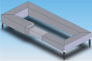
 At the beginning of our design process, which was around September 2008, we had no clue at all of how to start. What kind of design we would want to go for. Then, our advisor Prof Chang Hwan Choi sent few pdf files about different wind tunnel that already in the market. From there, we decided on going for IWT that lay down on the floor with 5 feet tall.

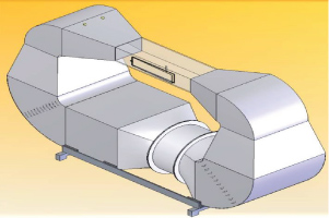
During second phase, we were concentrated doing the calculation for estimated wind speed, required mass flow rate of water, the materials and also targeted low temperature. Then we picked our components off the shelves based on our calculation. So the overall design of ducting need to be changed. We decided that it’s better to have the fan on the floor due to stability of system and have everything else be on top of the fan and evaporation system. Although we wanted to go for round ducting, but at that point, we could not contact any respective ducting company that’s willing to do the custom-made ducting for us.

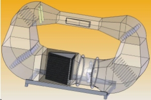
The diagram above showed the transparent view of our second design. We made the solid works model of the inside components. Observe how the fan was located next to the evaporator system. Turning vanes were placed at the all four corners to increase the straightness of the wind flow after the turn. The nozzle system was located before the test section.

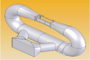
However, we came to realize that there was a problem with our previous design. The evaporator might turn into a chunk of ice in seconds because of imbalance conservation of energy. Once the tunnel cooled down to our desired temperature, the additional heat that’s coming from the water nozzle will cause the heat in not equal to heat out across the evaporator. So we had a long meeting with Mark Byrd, discussing about the problem. Then we came out with the second loop system that will eliminate the issue. He also talked about getting round ducting for our design instead of square ducting so that we could reduce the turbulence in the tunnel. Also, he recommended a ducting company that could do the job for us.

The third design was too tall in height that it interfered with the ceiling of the room that it will be located. So we have to redesign the IWT to horizontal lay out. The dimension of the ducting was reduced from 24 inch diameter to 12 inch diameter as the commercial HVAC ducting that’s available off the shelve is 12 diameter. We also had to design the base section to support the IWT.